


John Standfield
1838 - 1890
John Standfield was born at King’s Newnham, Warwickshire, on the 23rd of July 1838. His early professional experience was gained in Canada, where he was employed on the construction of the Grand Trunk Railway, chiefly in connection with the Victoria Bridge, Montreal. On returning to England in 1861, he had the superintendence of sinking the caissons for the foundations of the London Chatham and Dover Railway Company’s Blackfriars Bridge; and in 1864-66, Messrs Peto and Betts entrusted him with the same duties on the widening of the Victoria Railway Bridge at Pimlico.

")
Mr. Standfield subsequently had charge of Mr. Rammel’s Pneumatic Railway under the Thames from Waterloo to Whitehall, but on the abandonment of the works he devoted his time to the study and development of various inventions, which he afterwards turned to account, until in April 1869 he proceeded to Bombay, as Resident Engineer for Mr. Edwin Clark’s hydraulic-lift graving-dock at Hog Island, which work he successfully carried out, returning to England in 1872.

Shortly after this, Mr Standfield entered into partnership with Mr Latimer Clark, and devoted himself more particularly to the study and improvement of floating dry-docks and hydraulic canal-lifts, and, in conjunction with Mr. Clark, became the inventor and patentee of several novelties in connection with this branch of engineering.
The most important of these inventions were: the gridiron depositing docks, constructed for the Russian Government, at Nicolaieff, on the Black Sea, and at Vladivostok, the designs for which Mr. Standfield submitted and explained to the late Emperor of Russia; a gridiron depositing dock at Barrow-in-Furness; hydraulic canal lifts erected at Les Fontinettes, near St. Omer in France, and at La Louviere in Belgium; and the off-shore dock, the first of which was built at Messrs Standfield and Clark’s engineering works, at Grays, Essex, and was launched and towed to Cardiff in June 1887.
A second dock of the same class was laid down, from Mr. Standfield’s designs, at Hamburg, and is believed to be the most rapidly worked floating-dock in existence.

Mr. Standfield also gave much attention to the raising and recovery of sunken vessels, and exhibited working models of his patent appliances to H.R.H. The Prince of Wales at the Westminster Aquarium. He was applied to by the owners of the S.S.AUSTRAL of the Orient Line, a vessel of 5,588 tons register, when she sank while coaling in Sydney Harbour in 1882, and succeeded in raising her without injury. Mr. Standfield contributed a paper (Ref. l) on this work to the Institution, for which he was awarded a Telford premium.
It was, unfortunately, in connection with this class of operations that his useful and energetic career was brought to a premature close, at the age of fifty-one.
In 1888 the S.S. VILLE DE CALAIS, a petroleum tank vessel, exploded and sank in Calais Harbour, and Mr. Standfield some time afterwards purchased the wreck, with the view of raising the undamaged portion which contained the engines and boilers. This after a considerable expenditure of time and money, he succeeded in doing, after cutting off the damaged bow-portion of the steamer and building a bulkhead across her.
On Saturday evening, March 1st, 1890, she was got under steam, and also taken in tow by a powerful tug, with the intention of bringing her to England. Early on Sunday morning, 2nd March, a sudden storm arose, and breaking away from the tug the vessel became unmanageable; an attempt was made to leave her in a boat, which capsized in lowering, and Mr. Standfield and three of the crew lost their lives. The vessel shortly foundered about a mile off Margate. Mr Standfield’s body was recovered the following morning off Deal, and was interred at Norwood cemetery on the 8th of March.
Mr. Standfield was elected a Member of the Institution on the 12th of April 1881.
Extract from the Inst.C.E. Mins of Procs. vol.101. 1889-90, pp.301-302
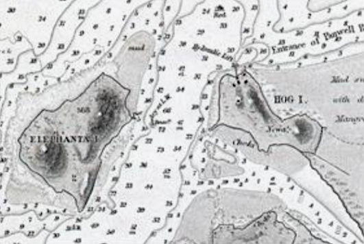
Hog Island
The Marathi name for the island is Nhave. It got an English name because it was here that ships used to be hogged, that is laid on one side and scraped. Mr. James Douglas. (T. Panvel), with a population of 1,875 in 1951 lies in the Bombay harbour about ten miles east of the Apollo Pier. The rock is chiefly black basalt which appears not only in viens and dykes, but forms the highest masses of the island, and even presents little headlands towards the harbour. Jour. Bom. Br. Roy. As. Soc. VI. 169. The Hindus have two names for the island, DevadevI and Nhave. The Portuguese called it Ilha de patecas,or water-melon island, a name which appears in Fryer’s (1680) Putachoes. Da Cunha’s Bassein, 204, Fryer’s New Account, 62, 76. It seems to be Hamilton’s (1720) Salvageo ‘about a league from Elephanta and affording nothing but firewood. New Account, I. 242. It was ceded to the English by the treaty of Salbai (1782 Nairne’s Konkan, 103.) The following account of the hydraulic lift as given in the old Kolaba Gazetteer (1883) makes an interesting reading even though the lift is not existing at present.
Hydraulic Lift.
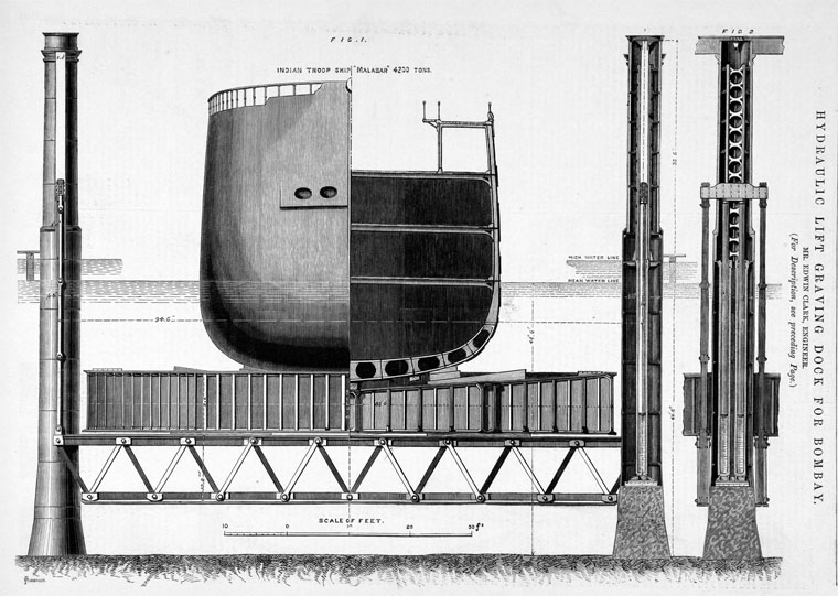
“The Contributed by Mr. F. B. Maclaran, C. E. chief object of interest on the island is the Hydraulic Lift Graving Dock. Before the Suez Canal was opened, the yearly military reliefs between England and India were carried by five troopships, of which two worked on the European side and three on the Indian side of the Isthmus of Suez. A special dock was required for the three troopships doing duty on the Indian side, as the depth of water over the sill of the Bombay graving dock could admit them only at exceptionally high tides”.
“About 1866-67 a committee was appointed to advise on the best form of dock. After visiting some of the most important graving docks in England they recommended a Clark’s Hydraulic Lift like one then in use at the Victoria Docks on the Thames. A Clark’s Lift large enough for. an Indian troopship was ordered, Mr. Edwin Clark, Mem. Inst. C. E., being the Engineer, and Messrs. Emerson and Murgatroyd of Stockport and Liverpool, the contractors. An engineer was sent from England to choose a site fixed on the north shore of Hog Island, about eight miles east of Mazganv, where there is deep water close to the shore. Whether this site is the best that could have been chosen is a matter of opinion. There is no doubt that the distance of Hog Island from Bombay has. in a great measure, led to the practical abandonment of the dock.”
“Most graving docks consist of a basin into which a ship is floated during high water. The gates are then closed and the water discharged either by gravitation as the tide ebbs, or by pumping. As the water sinks, the ship is shored by timber against the sides of the basin. The Hydraulic Lift Graving Dock is on a different plan. Instead of the water being removed from the sides of the ship, the ship is lifted out of the water.”
“The Hog Island Lift consists of two rows of hollow cast-iron columns, six feet six inches in diameter, sunk to a solid foundation at depths varying from fifty to seventy feet below high water level. The two rows of columns are eighty-eight feet apart, and, in each row, the eighteen columns are eighteen feet apart at the centre and twenty-four feet apart at the ends. Inside of each column a pair of hydraulic presses and rams. fourteen inches in diameter and having a stroke of thirty-four feet, rest on a bed of Portland cement concrete. To the top of the rams, Hat iron chains are fastened by strong iron cross-heads, and, at the lower ends of toe chains, wrought-iron girders stretch under water across the lift from one row of columns to the other. These girders arc of the Warren girder type twelve feet deep and of great strength. There are thus eighteen pairs of girders forming a sort of grid between the two rows of columns. The rams are worked by hydraulic pressure from two pairs of powerful steam pumping-engines placed in an engine house on shore, the water being supplied to the pumps from an overhead tank and carried in pipes from the pumps to the rams under a pressure of 17 cwts. the square inch. The pipes are laid along a gangway eighteen feet wide and 200 feet long, supported on cast-iron columns two feet three inches in diameter, which forms a passage between the lift and the work-shops on the shore. At the outer end of the gangway is a valve house, with an ingenious arrangement of valves, whereby one man” can with ease shut off or apply pressure to the presses and rams at any part of the lift. These valves are further divided into three groups in such a manner that in lifting a ship, should the weight be uneven and the rams not be working at the same rate, one man can by manipulating the valves bring the whole to one level.”
“Attached to the lift is a pontoon, or tray of wrought iron, eighty-four feet wide and 380 feet long, with sides nine feet deep. This tray is made of longitudinal and transverse wrought-iron girders and plating, and is divided into bays or chambers by longitudinal and transverse bulk heads. At the bottom of each chamber is a large valve which allows water to pass out or in. When a ship is to be docked, the pontoon is brought into position between the rows of columns and over the transverse Warren girders which are raised into position to receive it; the valves of the pontoon are opened and it is quietly lowered into the water. When the pontoon is deep enough the ship is brought over it, and the pressure being admitted into the presses, the pontoon is raised until the keel of the ship bears against the keel blocks previously arranged along the centre of the pontoon. Sliding bilge blocks, with which the pontoon is also fitted, are then drawn up by chains leading on to the side platforms of the lift, and the ship being safely berthed on the pontoon the whole is lifted out of the water. As soon as the ship and pontoon are clear of the water, any additional shoring that is necessary is put in, the pontoon valves are closed, and the whole lowered. This time the pontoon floats with the ship on it, and as it does not draw more than six feet, it may be towed to any convenient shallow basin. The lift is ready for another pontoon and another ship. The time spent in actual lifting is about twenty minutes, and for the whole operation not more than an hour and a half. With two pontoons in readiness there would he no difficulty in lifting and docking two ships on one tide.”
“To help the working of ships and of the pontoon in and out of the lift, powerful capstans have been set on large cast-iron cylinders, twenty-two feet in diameter and filled with concrete, two being at the west entrance and one between the lift and the shore. A steam capstan has also been provided at the shore and at the gangway, and snatch-heads and bollards on the plat-forms on the outer sides of the rows of columns.”
“The work was begun in 1869, but, owing to delay in receipt of material, it was not in full swing until November 1870. It was completed in September 1872 and was taken over by a committee appointed by Government on the 12th September 1872. On this occasion the Resident Engineer and contractors were anxious to prove the usefulness of the work by lifting a ship. Government ordered the turret ship Magdala to be held in readiness, but it was afterwards feared that, if lifted out of the water, the Magdala might be strained by the weight of her armour plating. As no vessel was available, the strength of the lift was tested by raising the pontoon full of water, a weight of 8,100 tons or 62 per cent. more than the weight of the heaviest troopship.”
“The cost of the lift with pontoon and other apparatus is supposed to have been about Rs. 30,00,000. The exact figures are not available, as nearly the whole amount was paid in England by the Secretary of State. The work in India was supervised by Mr. J. Standfield, C.E., Resident Engineer, Mr. F. B. Maclaran, C.E., being the contractors’ agent, and Lieutenant, now Captain, Haydon. R.E., Executive Engineer, representing the Government of Bombay”.
“By the opening of the Suez Canal the necessity for docking troopships in India ceased. For the same reason, ships of the Mercantile Marine which were formerly docked in Bombay have their repairs done in England. On this account, and, because of its distance from Bombay, the Hog Island Lift has been little used. When it has been used the machinery has worked well.”
Article sourced from the Kolaba District GAZETEER
References:
Minutes of Proceeding Inst. C.E., vol. LXXIV p. 246.